Upgrading a Philips-Fluke PM6665 Frequency Counter with an Oven Controlled Crystal Oscillator - Up and Running!
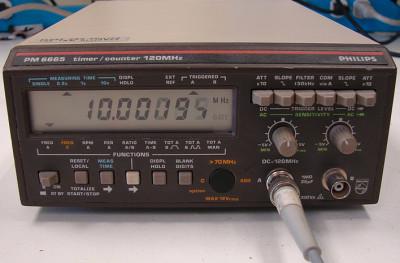 I needed a frequency counter for my little lab at home. Naturally, I wanted an HP Agilent 53132A or similar, but it’s way too expensive for my modest use. So I browsed around eBay and found an old Philips-Fluke PM6665 frequency counter with the optional 1.3GHz add-on board. With a 10 second gate time, I can get down to 0.1 Hz at 10 MHz, so that’s more than I need. It didn’t have the option of a better crystal, unfortunately. When I tested the PM6665 against my Trimble 10 MHz GPSDO reference, the unit was off by 200.1 Hz. Without a calibration sticker on the instrument, I’d say that’s pretty good for a device manufactured in the late 80s. I tried to trim it, but it uses an adjustable capacitor, and you only needed to look at it for it to change settings.
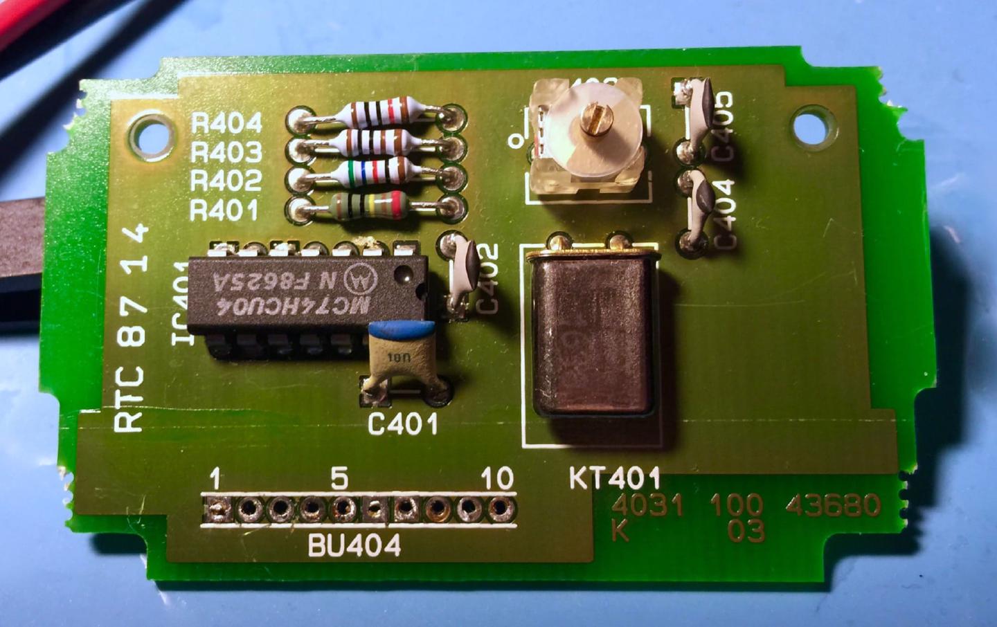
The other problem was the temperature difference when having the unit open for calibration. As soon as I closed it, it started to drift. There is an input on the back of the unit for a lab-reference 10 MHz signal so I could connect my GPSDO to it, but I wanted to see if I could get good precision on it as a standalone unit. There are a lot of salvaged components available on eBay from old cell-towers and other equipment that need precision timekeeping. So for around $15 you can get a 10 MHz crystal ovenized oscillator. They look like they’ve been removed with a crowbar. But the two I bought has been working flawlessly. And just like with old wine, a crystal gets better with age.
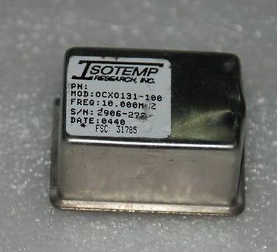
One of my favorite YouTubers, Gerry Sweeney, go and subscribe! Upgraded his old Racal-Dana 199x with a 5V ISOTemp OCXO131–100.
https://www.youtube.com/watch?v=B_Y971uY3Nk
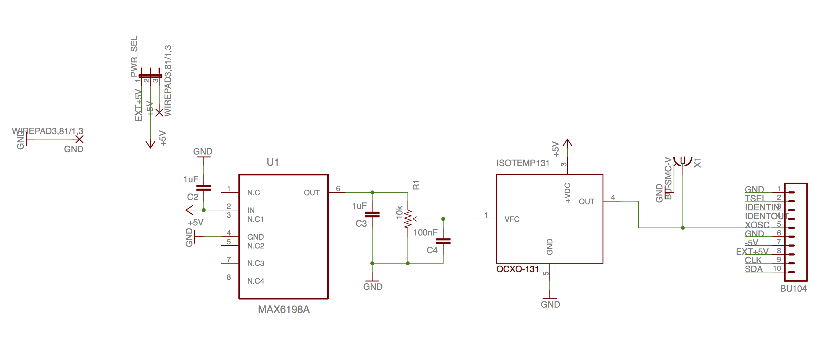
So I modified his circuit to work with my old Philips PM6665. It uses a MAX6198A as a voltage reference for calibration. It has low drift from temperature differences, 5ppm/°C (max) Temperature Coefficient and ±2mV (max) Initial Accuracy, so It’s a perfect fit for using as a calibrator for the voltage controller pin on the OCXO. The trimpot also has drift due to temperature, but when the unit warmed up in about 15–20 minutes its super stable. There is a built-in calibration in the frequency counter, but I couldn’t be bothered trying to decode the serial traffic between an old 8-bit processor and the board.
I designed the PCB using the (not so well scanned) service manual as a reference because I still hadn’t received the unit sent to me from the seller in Canada. A weird side story. My counter turned out to have been manufactured just a couple of kilometers from where I live here in Sweden. So in a way, it finally came home again. (Ah, the good old days when we manufactured electronic equipment.)
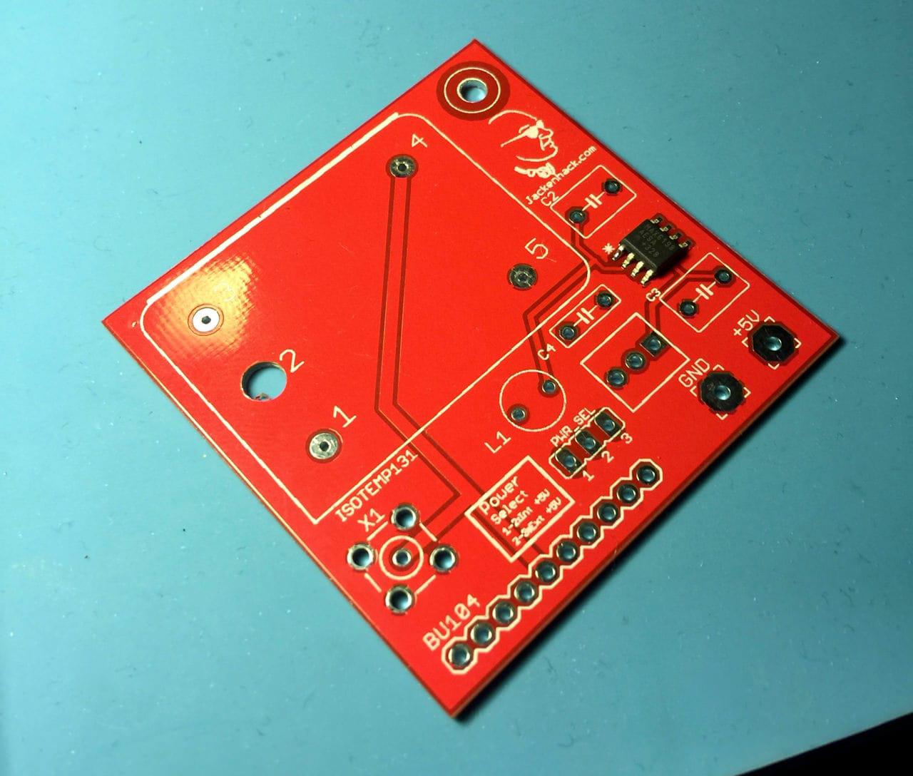
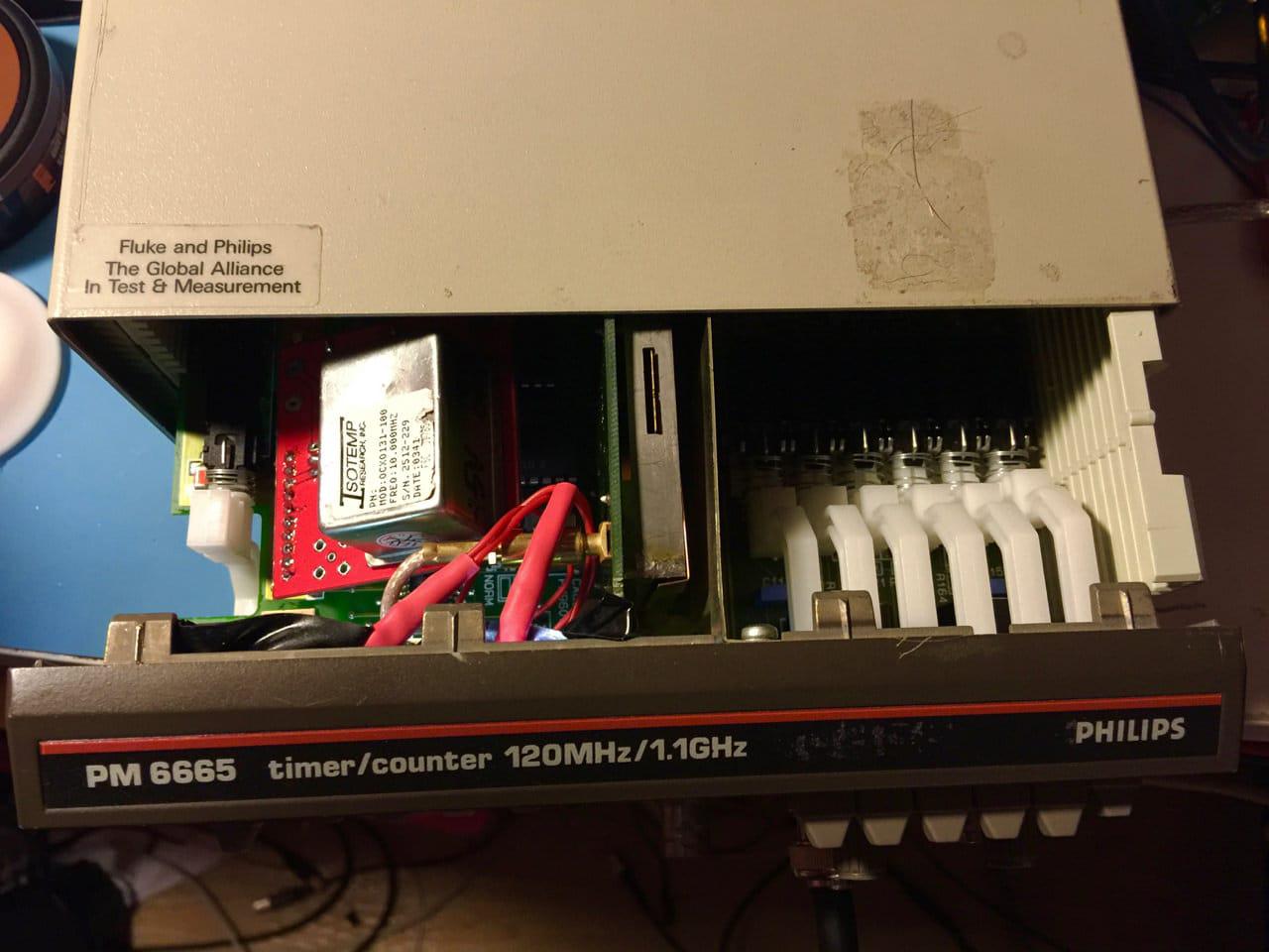
After reading the schematic, I was confident of the placement of the board. But I was wrong. My design was counting on that the oscillator board would be horizontal, but naturally, it was vertically mounted. That was a stupid mistake. No problem, I just had to bend the connector socket, installing it at an angle and everything was hunky dory. Well, one of the mistakes. I forgot that it was mirrored when making the package for the ISOTemp unit in Eagle PCB, Easily fixed, just solder it on the backside! (fixed in the new version below).
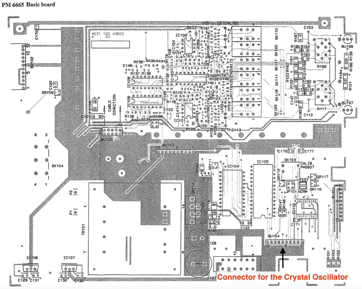
The PM6665 has an LCD screen that isn’t backlit, so I added two white LEDs. That turned out quite well. Now I can see even in low light. There’s a connector to the front panel where pin 9 is +5 volt and pin 1 & 10 are GND. I was a little bit worried that the weak old 7805 DC regulator would go berserk with all the extra current being drawn, both from the OCXO (600 mA on turn on, stabilizes to around 250 mA when up and running) and from the two LEDs, but It seems to work correctly. I added an extra 5 Volt supply connector to the PCB if there would be a problem. While at it, I also added a place for an SMA connector for the 10 MHz signals if I want to use the card for something else.
The Schematic
Here’s the schematic with the 10-pin female connector (I desoldered the original and put it on my new PCB). As you can see, there’s a header for choosing where to get the power. Either from the main board or your supply. I use the +5 Volt from the connector without a problem (so far). If you want to go fancy-schmancy, you could build a 5-volt regulator with filtering, etc., but I’ve been running the counter for days, and after calibrating the OCXO using an oscilloscope (more comfortable and quicker), it’s been rock solid.
A New Schematic and PCB
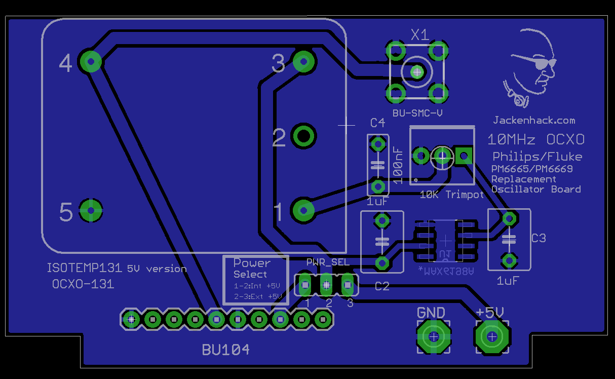
I’ve designed a single sided PCB in Eagle PCB with the correct size and orientation. Download it and go nuts. It’s pretty Schmick to have an old instrument perform like it’s 1999!
Result
The warmup time is about 10–15 minutes, but if you want to be sure, give it 30 minutes (or leave it on, it has no fan, so it’s dead silent).
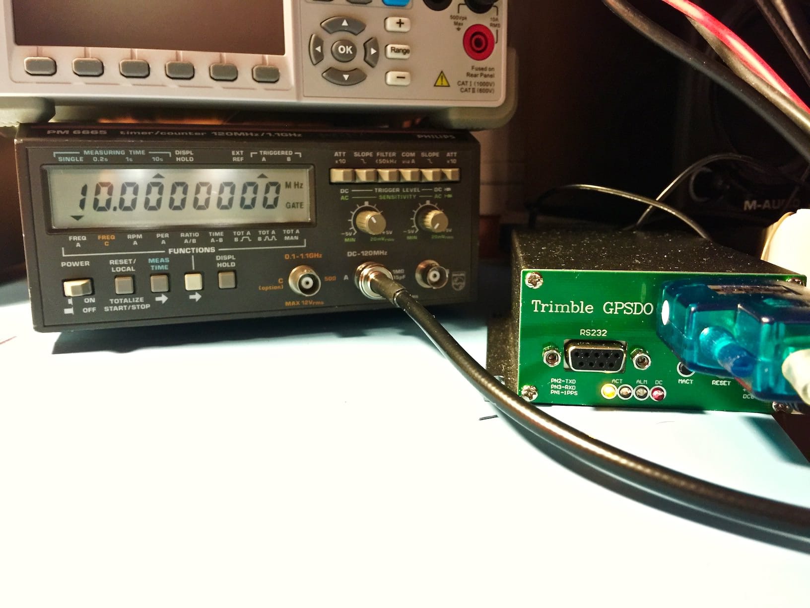
Here’s the device connected to my Trimble GPSDO and this is after two days, and not a flicker of deviation from the calibration. When feeding the counter from my Siglent SDG2122X, it shows an error of 2 Hz. Until I enabled the external GPSDO reference on the Siglent signal generator. Then it’s dead on from 1–120 MHz. I’m pretty impressed with the Siglent SDG2122X, 2 Hz off with its internal non-ovenized crystal is pretty good.
(Ohh! Look at that lovely backlight!)
Don’t Forget!
You need the ISOTemp 131–100 5 volt OCXO version!
Download Eagle PCB Schematic and PCB Design Here
Download the Eagle schematic and PCB here.
And here’s a tip, just upload the board file to DirtyPCBs. They automatically make the Gerber files needed. You get 8–12 boards for about $25 including shipping, and they haven’t failed me yet. You can even select the PCB color!
Happy Hacking!
Hi Jack, I was so stoked by your great article, I went to eBay and bought a PM6665. While I am waiting for it, I downloaded the Eagle file schematic for the small board on which the ISOTemp 131–100 5 volt OCXO is mounted.
Do you by chance have any of those boards left that you would like to sell? If so, please send me a direct email address for you and we'll make a deal.
Thanks!!
I've sent you an email.
I am one of those "poor souls" who has the cheapest version of that counter family, the Fluke/Philips PM6662. Its crystal drifts a lot, really. To bad it does have 9 digit resolution. What a waste ;-) If you still got one of those PCBs left, and a parts list, I would like to buy one from you, just e-mail me...
Thanks ahead.
Kind regards
Check your email.
The i2c calibration isn't trivial : it's called an MCXO (mathematically compensated crystal oscillator) and contains an i2c temperature sensor and an NVRAM. The NVRAM contains a list of corrections to be made according to the temperature of the oscillator.
Sounds straightforward and is probably at least as good as a TCXO, but I don't know how you get the list. Presumably you need to run the crystal over a range of temperatures, measure the error, and record it in an appropriate format.
An OCXO, given the price you can get them for now, is a sensible and probably more accurate alternative.
Because an OCXO usually delivers a much better performance compared to a TCXO or MTCXO, it's probably not worthwhile to go after the original version or designing something similar yourself. Depending on the counter you got you mainly have to look for an 5VDC OCXO (height) which fits the space provided for the original option module. I fitted one myself for the PM6662 I got, which greatly improved on its accuracy...
I notice that you mention the backlight. My PM6666s don't have that : is it a feature of the PM6665 or a mod you did ? If you added it, would you like to document it ? !
Hi! I used two white LEDs, tapping +5 volt from (check the schematic to be sure) pin 9 for +5 Volt and ping 1 or 10 for GND. Just add a drop resistor in line so you don't blow the LEDS. I hot glued them after using sandpaper on the LEDs to make them scatter light in all directions. Works a treat!
Hi Jack,
Great project, I will upgrade my PM6669 and just ordered PCBs. I had a look at the MAX6198A datasheet, it specifies a capacitive load stability range of 0 to 2.2 nF, so I think it would be better to use a smaller C3 value than 1 uF, perhaps 1 nF. What do you think?
Best regards
Hi! Great to hear that you ordered the PCBs. If you want to get rid of the excess cards (you usually get 10-12 cards from DirtyPCBS), I can redirect people wishing to obtain a PCB. I have at least two requests for the cards.
Yes, but I would stack both a 1 nF and a 1 µF capacitor. You can solder them on top of each other, with the 1 nF at the bottom, closest to the output. I've been running my frequency counter for one and a half year, and haven't needed to recalibrate. I usually use the 10MHz reference input, but sometimes I check it just for fun, and it's still spot on.
Yes, I would be glad to get rid of the excess cards, please feel free to forward requests. The boards were ordered yesterday at DirtyPCBs, color is black, price would be the original price (approx. 2 USD per board) plus shipping (letter from Germany).
Hi, great project! I would like to upgrade my PM6669 this way. @Jack, could you please forward this to Ernst: If there are still excess cards available, I would like to buy one or two. Thanks!
Best regards
Hi,
Well done, great project!
I would also like to upgrade my PM6669 that way. @Jack: could you please forward my mail to Ernst, maybe he has some pcb still available, I would love to buy one...
Thanks a lot and best regards
The original oscillators used in this design are getting difficult to find, the good ones anyway, so I built a PCB using a AOCJY3=A module from Mouser, and it doesn't work. The OCXO is warming up and I can see a 5.2V 10 MHz signal on the output pin and the via close to pin 5 so the signal is getting in, but the counter does not start. Replacing the original TCXO restores operation so nothing is blown.
Please could you confirm that pins 1 and 6 are the only pins connected to ground? Gut feeling tells me that this is something to do with the mode select pins.
Peter
According to the spec sheet for that OCXO, with 5 Volt supply, the output is 4.6 Volts. It outputs 5 Volts if you feed it 12 Volts. Not sure if that's the problem. The PM6665 uses the OCXO as the processor clock as well as the counter reference. So if the counter doesn't start, there's a problem with the clock.
Pin 1 and pin 6 are connected to GND.
Does anybody has an extra pcb, I only need.one.
hello , good job, I just got an PM6665 at 20 bulks including shipment, no power, no display as seller indicated. guess what, the DC power works well, since there is no power on LED, everything shown on TN LCD panel...
before open the cover, I presumed the worst case is Fuse was gone, I did check the transformer . no sign shown blown fuse, All the PWBs have good condition, only minor duct. Disassembled the display module, clean all the contacts, Fire it up, it works again, turn out the contact between ITO with flexible conductor almost no contact, because the screws are not loosen. clean-up and feed signal, good unit.
I am wondering, why no back light for such instrument?? then do some google "Philips PM6665", i found your web pages, GREAT !! the answer already in the reply area.
But I have ot mention, I did stupid actions, when I do the LED back light mod, 1) the 5V pin is totally, wrong, it should be Pin9 , since I read the schematic, 5V goes to IC Pin5, I did solder to PIn5, of course, LED never light UP 2) after rechecked , why did I do such stupid action, re-connect LED plus to Pin9, but still no LIGHT, 3) the pin assignment really confused me, anyway, reconnect to correct Pin9, now it lights up. anyone wan to do the mod, be careful to pin assignment, Luckily again. no burn was caused by these errors,
Question Does anyone know howto remove the nob of sensitivity Potentialometers, I force to remove it, and unscrew the front nut then take off all, however after i first return all the nub parts, I can't take it off again, I tried harder, then all nub parts were removed from shaft, the nut and parts I do not know how to name it, stick inside the plastic nub, how to fix it, thank you very much CS
after all this time, I actually found your page once I purchased an old 6666... and I was wondering, would you still have one of those boards? I am in Italy! I have a soft spot for old Philips gear, even tho I own a HP 34401A I still sometimes like to use my salvaged PM2534 DMM. I think I will also try to mod it so that the LCD is going to be visible. But, please tell me you still have one of those OCXO boards!
Best,
Franco
I'm Italian, I have a 5351B without the OCXO option, I would be interested in a PCB if available.
Hello, I've got a PM6662 which drifts like a hell... If you have a spare unused PCB I would be interested. Thanks in advance. Olivier
Hai,
I just bought a PM6669/431. I'm also interested in a spare PCB if anyone still has one laying around... That would be great!
Thanks :)
Richard
Hallo,
I bought a PM6665 . I’m also interested in a spare PCB if anyone still has one laying around… That would be great! I am in Germay Thanks
Horst