 How to add an I2C interface to a Sonoff WiFi Smart Switch.

The Sonoff brand is a whole series os IOT devices that use the esp8266 WiFi processor internally. The devices are easily hacked and are cheap. The Sonoff WiFi Smart Switch is the most straightforward device, which can turn on or off 110/220 Volt 10 Ampere remotely. That means you can have your ceiling fan, lamp or anything else connected t mains power remotely controlled by your phone or computer. But the software that comes with it isn’t very flexible and cannot be integrated into a home control system like NodeRED, OpenHAB or any other home automation system.
Firmware
The Sonoff devices are easy to hack, so you can put a better firmware like ESPEasy on it and integrate the device with any system. ESPEasy has an extensive list of extra modules that you can connect, like temperature, barometric pressure, humidity, light sensors, PIR sensors and a long list of other things.
But most modules connect with I2C, which is a serial interface for interconnecting ICs using a clock and a data line. The Sonoff Switch only have one extra pin available, making it impossible to connect more advanced sensors. But there is a way of fixing that. Here’s how to add that to add an I2C connector to your $5 Sonoff and open up a whole field of stuff you can do.
Let’s upgrade the firmware!
To be able to upgrade the firmware, you have to open the enclosure and find the five holes in the center of the PCB and solder a female header for easy programming. As you can see in the picture, I’ve already soldered in a 5-pin header. (Click image to enlarge). I have marked the pinouts in the i.
 To be able to program the new firmware, you need a USB to TTL Serial Adapter. You need an adapter that is 3.3 volts compatible. Connect the 3.3 Volt on the USB adapter to the 3.3 Volt input on the Sonoff. Do the same for ground. RX on the adapter should go to TX, and TX on the adapter goes to RX. Yes, they are crossed over, too young to remember RS232 and Null-cables, you whippersnapper?
But don’t connect mains power! You should never have the Sonoff device connected to mains power when upgrading firmware! The USB Serial Adapter provides 3.3 Volts needed by the esp8266. Doing it wrong is a good way of getting a punk hairdo or maybe wings and a harp…
Now, all you have to do is to download the firmware and follow the instructions here to install it. The size of the memory on the Sonoff WiFi Switch is 1024k as standard. Either do the upgrade with the available memory or maybe you want to increase the memory of your Sonoff? Read on…
Upgrading The Memory
If you want to make your Sonoff future-proof, there is a way of updating from 1MB of memory to 4MB. This is handy as the ESPEasy firmware evolves and get’s more substantial. Or maybe you want to write your own code and need the space? If you plan to do OTA[1], you need double the memory of the size of your program. You can do wireless updates without having to resort to using the USB to Serial adapter after the first install. This isn’t a must because ESPEasy works with just 1MB, but it’s better to have 4MB.
I prefer to isolate plastics and other heat sensitive parts with heat resistant Capton® tape. I use a hot air soldering station to remove the old memory IC, but you can use a soldering iron. Just fill the tip of the iron with a big blob of solder and heat all of the legs on one side of the IC at the same time while bending the chip up carefully with a screwdriver. Then you do the same thing on the other side.

The replacement IC is called Winbond W25Q32FVSIG, and you can get 10 of them for around $3 on eBay. Make sure that the dot-marking indicating pin 1 is lined up correctly and solder on the new IC. Now you have a 4MB Sonoff! Naturally, if you flashed the firmware before upgrading you need to flash the firmware on the new memory chip.
Sonoff WiFi Smart Switch with I2C
Now let’s add I2C to the Sonoff Switch.
You’ll find the esp8266 IC on the underside of the PCB. We need to solder two small wires to the pins on the esp8266 to get I2C. We need to solder the wires directly to the esp8266 IC because the pins are not connected to anything on the PCB.

The processor doesn’t have hardware I2C support, so you can use two free pins to connect, but usually (and in ESPEasy), GPIO4 and GPIO5 are used for I2C connections. Here I have soldered a thin wire to pin 24, which is GPIO5(SCL).

After you soldered the wire, make sure to glue the wire to the PCB. Hot glue works fine. This keeps the wire in place and doesn’t snap when routing the wire later. Then I soldered a wire to pin 16, which is GPIO4(SDA) and hot glued it to the PCB. You now have the hardest part done!

Yeah, it looks like an enormous amount of glue, but it’s a couple of millimeters.
You need a good magnifier glass or preferably a microscope designed for working with SMD components.
If you use thin wire, you can just take it up between the enclosure and the PCB. I added a 4-pin female header connector and soldered a 90-degree male header that I connect to the programming pins. Then I just soldered the 3.3 Volt, GND, the two I2C wires to the connector. Everything you need to connect a module using I2C.

Configuring ESP Easy
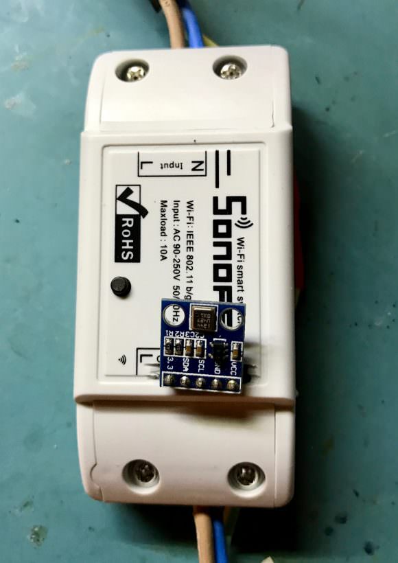
Now it’s time to try it out. After you’ve done the initial setup of the Sonoff device, select “Devices” in the setup menu. Select the sensor you just connected to your Sonoff. In this case, I have attached a BME280 Temperature, Barometric Pressure, and Humidity sensor.


-
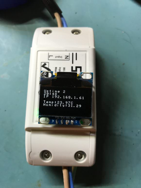
- Sonoff I2C OLED Display
-
- Sonoff I2C BMP180 Sensor
-
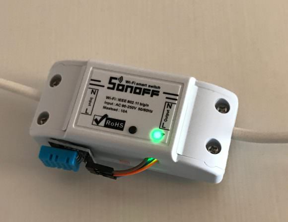
- Sonoff HT11 Sensor
- Over The Air updates. A way of programming the esp8266 via WiFi instead of having to upgrade with a USB to Serial adapter cable. ?
Paul says
Nice! Thank you for publishing this clever mod 🙂
Pescatore says
Very interesting modification. I am thinking about trying it myself and I have a couple questions.
I guess the factory firmware gets blown away, so the phone apps that iTead offers will no longer work?
The OTA link loops back to the top of your post. Do you have a link where I can learn about adding this
functionality?
I also found a tutorial on the iTead website about modifying the Sonoff (https://www.itead.cc/blog/sonoff-tutorial-a-wi-fi-smart-switch-for-5). They seem to just upload new user code, but I don’t understand if the modules come with new firmware that can load user code. I am thinking that loading user code is only a piece of the firmware in the chip.
Thanks for hacking!
Jack Zimmermann says
Yes, the factory firmware is deleted when uploading the new firmware. But I think it won’t be missed. Even the iTead guys seems to understand that most people are going to hack the firmware. The ESP Easy firmware is easy to use and you have control over your data. You can always connect it to an outside MQTT service if you need external access or don’t want to setup your own server (but you should because it’s fun!).
The OTA is built-in into the ESP Easy firmware. Under one of the settings there’s an option to upload a new firmware version.
Good luck with your Sonoff Switch and be safe.
Jacken
BERNARD says
There is no need to solder wires on the ESP chip to get I2C GPIOs pins.
Once you have installed ESPeasy you just have to reconfigure RX and TX into SDA and SCL.:
1- in the menu Tools -> Advanced you untick Enable Serial Port, this will free GPIO1 and GPIO3
2- in the menu Hardware you allocate SDA and SCL to GPIO1 and GPIO3
That’s it
Jack Zimmermann says
Yes, your absolutely right, that’s a great way to do it. For me, I needed more GPIO pins available for different sensors, so that’s why I did it this way.
BERNARD says
Without soldering on the chip (very tricky) I believe you can get 2 other GPIOs:
– GPIO 0 : if you don’t need the switch
– GPIO 13 : LED pin
I hav’nt yet tried
Jack Zimmermann says
Just remember that if GPIO 0 is high at startup, the unit goes into boot loader mode…
Duncan says
Worth pointing out that this will be 3.3V I2C, not the 5V that many devices require…
Bruno wladimir de oliveira says
DOES HE HAVE ANY ANALOG PIN?
Frak says
How did you get the temperature and humidity for the one with the OLED display? Isn’t it one or the other?
Larry says
So being a newbie with this stuff, I wanted to do some automatic temp control but didn’t know how to approach it. This seems like a viable option, what I would like to do is monitor the temperature of my fireplace .
.My fireplace has a snap limit switch that when it gets to its limit it will turn on the fan then off when it get to the lower limit. Problem is that it’s not all that responsive , sometimes it stays on and blows cold air.
So I would like to do is add a K thermocouple to the chamber where it reads temperature and control fan operation. I could also add a current sensor to monitor fan amps.