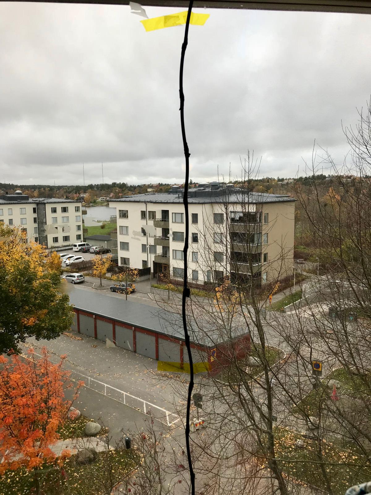
My first attempt of a Collinear Antenna. Professional mounting!
Part 1 – Checking the Velocity Factor of the Coax Cable
I have a homebuilt Collinear Antenna on one of my two ADS-B receivers. It’s an eight element antenna, built without any real effort of making sure that all the elements where the right length. So it’s about time to try to do it properly. The easy way is to get Flightaware’s great ADS-B antenna and filter, but it’s fun to build your own as well.
To build a good antenna, you would preferably use a Vector Network Analyzer so you can do proper measurements of your antenna design. With it you can quickly check stuff like SWR and optimize the impedance of the antenna at the frequency it’s intended to be used. In my case 1090MHz for ADS-B. But if you don’t have the money to spend, you have to improvise. I’m going to build a 12 element Collinear Antenna out of cheap RG-58 coax cable. But to calculate the right length of each element, we need to know the Velocity Factor, or the signal speed through the cable compared to light traveling in a vacuum. So let’s do the measurements.
The Cable
I got a long stretch of some old RG-58 coax cable from an old cash register. You could just go with the velocity factor values you find on the internet for RG-58, which the almighty Google says is 0.66. But using this value in my case would be wrong, and the calculations would end up with an antenna way out of the optimal performance, as we shall see.
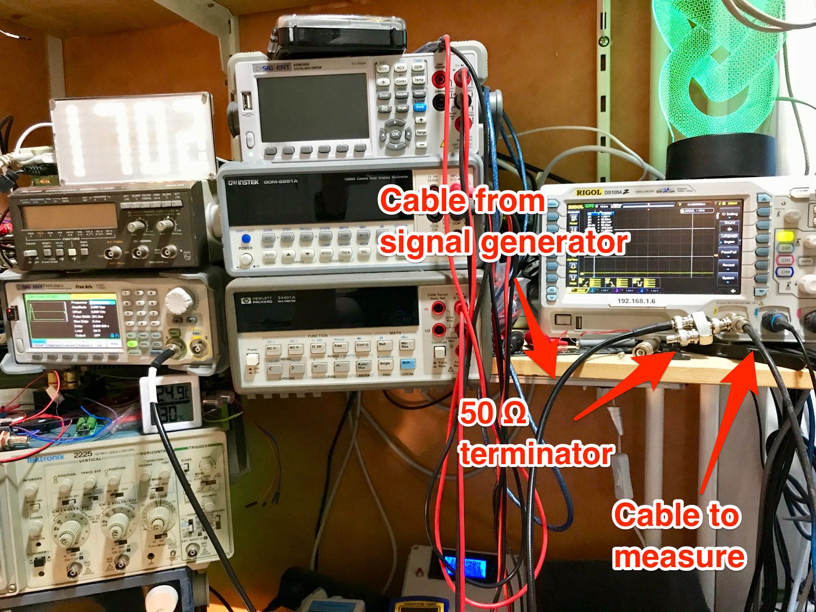
The Measurement Setup
Here’s what we are going to do. Send a pulse with fast rise time (in my case a pulse with 9.5 ns rise time) from a signal generator at relatively long pulses, in my case with a Silent SDG2122X 120MHz Waveform generator (Actually a hacked SDG2042X.) The pulse goes into an oscilloscope, with a T-BNC connection. Connect the coax cable to the other BNC connector on the T-connector. The pulse first shows up as a quick rise on the oscilloscope, but the signal will travel down the unterminated coax cable and reflect back. This will double the signal when it reaches back to the oscilloscope. So using cursors, we can measure the travel time of the pulse and divide it by two to get the propagation time.
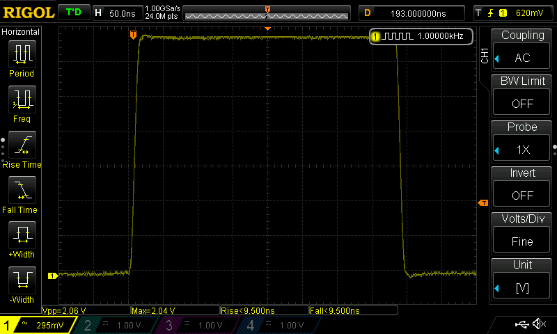
The pulse without the unterminated cable attached.
Ok, and let’s connect the unterminated cable. Now we see the adding of the returning signal from the coax cable.
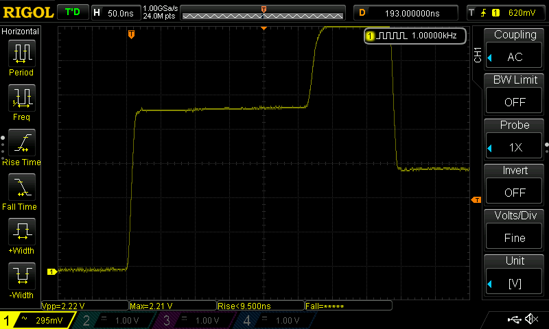
Pulse with return echo from an unterminated coax cable.
The pulse width should be long enough because we want to be able to measure short cables. If you don’t have a signal generator with a fast rise time (the quicker, the better), you can build a pulse generator with the swift rise and fall edges of about 1.2 ns for around a dollar. Here’s a video on how to create it.
https://www.youtube.com/watch?v=9cP6w2odGUc
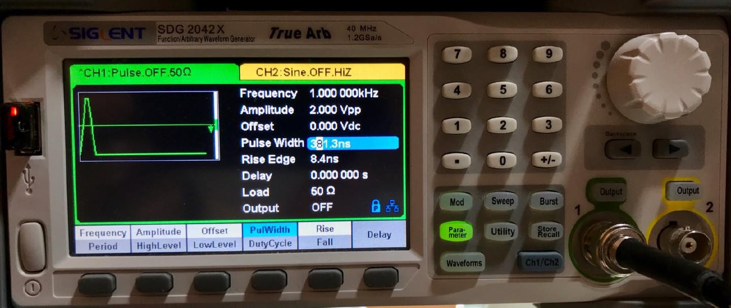
Here are the settings on my signal generator with 8.4ns rise time. I’ve set the output to 50 Ω impedance to match the connections at the oscilloscope.
Calculating the Velocity Factor of the Coax Cable
So now it’s time to use the cursors on the scope for measuring the time for the signal to go to the end of the unterminated cable and echo back.
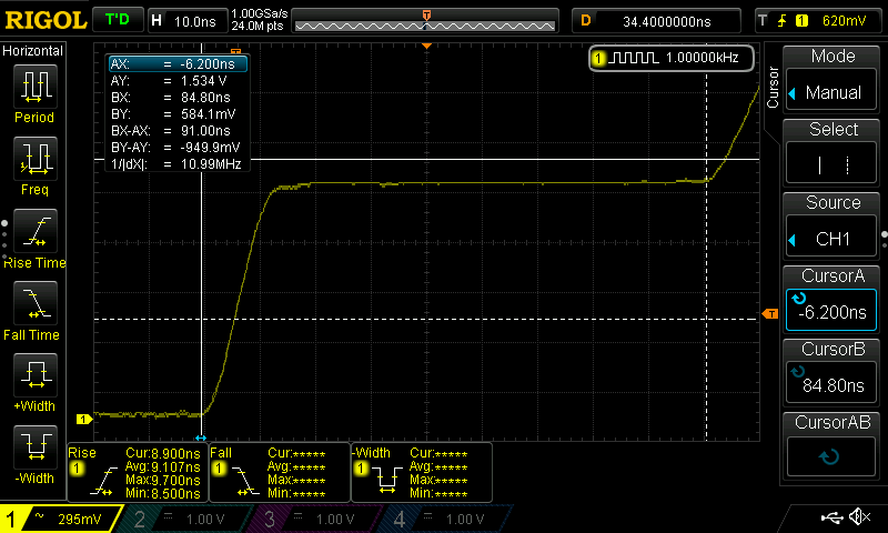
So the Δ between the start of the pulses are 91ns. The propagation time is half of that, 91÷2=45.5ns for the signal to go one way through the coax cable. The cable is 950 cm long and the distance light travels in a vacuum in 1 ns is 29.99709 cm.
950cm ÷ 45.5ns ÷ 29.99709ns = 0.696038 Velocity Factor. The factor is 0.696 times the speed of light.
Will the specified value of 0.66 and 0.696 VF make a difference when doing the calculations for the lengths of the sections of the antenna? Let’s check.
The formula for calculating the length of each element is:
λ = c / f
c = speed of light in vacuum 299 792 458 meters per second. f = Frequency, 1090MHz for ADS-B
λ = 299.792458 / 1090 = 0.2750389523 meter wavelength
Length of element = (half wavelength in meter) 0.2750389523 ÷ 2 = 137.5194761468 * (VF)0.696 * (convert to cm) 100 = 9.4888438541 cm
So the length of each of the elements should be 9.49 cm with this cable. But how much would it have differed if I used the official velocity factor from the manufacturer? Then the result would have been 9,08 which is almost 5 % off target. Will this make a difference? We’ll see when I build an antenna. You can find a handy calculator for calculating both ½ and ¼ wavelength for collinear antennas with build instructions here.
In the next installment, I’ll do the assembly of the antenna and make some comparisons against my FlightAware Antenna, and my old bodged together collinear antenna.
Hi Jack- tnx for sharing this information. Quick question: did you use 12 elements with equal length? Or did you use a quarter length for the first and 12th element?
I am asking this because this is what the calculator page you are referring to suggests. On other pages i found about building a coco this is not mentioned. (So I am a bit confused .. this is my first antenna project so there is a lot for me to take in :)
tnx!
When your segments are too long, you can cut them :-) I didn't understand which size ( 9.49 cm or 9.08 cm ) produced a better matched antenna ? I think to try this type of antenna at 868 Mhz. Is it suitable for transmitter or only for receivers ? Once I tried to make such antenna for 2.4GHz AP and it didn't work well. Probably due to not measured velocity.
The You can find a handy calculator for calculating both ½ and ¼ wavelength for collinear antennas with build instructions here. kink no longer works
Without having a ozi and signal generator, the optimal element length should have 1:1 swr right? So why not measuring the swr on a 1/2 lambda piece of koax cable to find out the correct length for the collinear? Does this work?
I just finished building a 1/2 wave 9 section coaxial collinear using RG213 cable. The 1/4 wave 12 section coaxial collinear using RG213 cable I built previously gets better range.